30+ Wiring In Series Diagram
The first is via a series connection the second is called a parallel connection and the third option is a combination of the two called a series-parallel connection. Varying voltages across each LED is okay.
Alternator Delete With Regen Braking Modification For Better Mpg Page 3 Mirageforum Com
Likewise one connected completely in parallel is known as a parallel circuit.

. The total resistance of a series circuit is equal to the sum of the individual resistances. Then we wire them in series by connecting the negative lead connected to aluminum foil to the positive lead of the other battery. A series testing board is a simple and very useful board for testing and further we use this board for different types of testing such a connectivity test.
We use to protect the circuit to connect fuse circuit breakers in series with other appliances. When the bulb goes out in a string of holiday lights it creates an open circuit in the wiring. This wiring allows for source voltage at each outlet independent of the others in the circuit.
If one LED fails the entire circuit wont work. The total voltage of the circuit is the sum of the voltages across each LED. Each diagram is used for a specific purpose and is designed to.
Web When a series LED connection is in question you will just need to replace the LED forward voltage with total forward voltage in the formula by multiplying FV of each LED by the total number of LEDs in the series. Web In this video were going to show you the differences between series and parallel wiring and explain which is better for your needs. Well also show you how to wire outlets in series and.
Web Here are a few bullet points for reference about a series circuit. Many circuits can be analyzed as a combination of series and. Web series and parallel circuits wiring.
Web This diagram shows the wiring for multiple receptacles in an arrangement that connects each individually to the source. High supply voltage are needed if we need to add more load light bulbs electric heaters air conditioner etc in the series circuit. GFCI and AFCI outlets are often connected in series to provide the same level of protection downstream to other regular outlets or loads.
Web How to Wire a Light in Series Robert Gibson Last Updated. Web Series circuits are somewhat rare in house wiring but they are sometimes used in strings of Christmas lights or landscape luminaries where one light bulb failing will cause the entire string to go dark. Wiring diagrams are embed.
Wiring lights in series means that all the lights in the circuit are connected along the same wiring path. Less size of wire cable is required in series wiring. Web The first thing you need to know is that there are three primary ways to successfully connect batteries.
Series connection of resistors. Web What is a Series Connection. These series resistors form a single path through which current can flow.
In the graphics weve used sealed lead acid batteries but the concepts of how units are connected is true of all battery types. The current is the same through each component in a series circuit Resistance. Series circuit dont get.
The two GFCI and AFCI can also be connected in series because they offer different types of protection against ground and arc faults respectively. A single-pole diagram a two-pole diagram and a three-pole diagram. The total voltage drop in a series circuit equals the sum.
How to wire batteries in Series How to wire batteries in Parallel. Web There are two ways to wire batteries together parallel and series. Learn to wire the beginningmiddle same outlets and the final outlet of the cable run.
October 16 2023 Toggle Wiring Lights in Series Wiring a Light in Series. Web Parts Tools 2 identical batteries Ill be using Chins 12V 100Ah LiFePO4 Batteries 1 battery cables the number of cables you need is the 1 less than the number of batteries youre wiring in series. Web Series circuits are useful if you want a warning that one of the components in the circuit has failed.
The illustrations below show how these set wiring variations can produce different voltage and amp hour outputs. Web Series Wiring is ALL or NONE type wiring mean all the appliances will work at once or all of them will disconnect if fault occurs at any one of the connected device in series circuit. In a series circuit the current passes through each component in turn with the same current flowing through all the components.
They also use less wiring than parallel close parallel Straight lines are parallel if they. Web The series wiring diagram shows how components such as resistors switches and lights are connected in a series circuit. Web Wiring Outlets in Series You can wire outlets in series.
Web 2023 Google LLC Wire Outlets receptacles in sequence. Web To wire a series of lights connect the positive end of one light to the negative end of the next light. Web A circuit composed solely of components connected in series is known as a series circuit.
Series circuits are easier to wire and troubleshoot. Web In this introduction to series resistance circuits we will explain these three key principles you should understand. Web In this lesson we go through how to wire a series and parallel circuit and start to understand what voltage will be at each load depending on which you useI.
Suppose there are 3 LEDs in series then this value becomes 3 x 33 99. Web When wiring lights in series there are three main types of wiring diagrams. All wires are spliced to a pigtail which is connected to each device separate from all the others in the row.
The same current flows through each LED. Web First we measure the voltage from each battery. Here we can see that two batteries one with 850 mV and one with 774 mV produce 1568 when wired in series.
The definition of a series circuit is a circuit where the components are connected end-to-end in a line as illustrated in Figure 1. This is a simple and cost-effective way to connect multiple lights such as in a hallway or along a fence line. Introduction to Series CircuitsA Series Circuit Example.
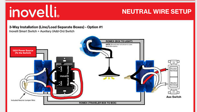
Nzw31 Sn 3 Way Config Lzw31 Sn 3 Way Config Wiring Discussion Inovelli Community

Series And Parallel Circuits Wiring Youtube

Switch Connection Or Wiring In Series And Parallel In 2023 Wire Switch Electrical Diagram Connection
1973 1991 Dual Fuel Tank Systems Theory Of Operation Page 4 The 1947 Present Chevrolet Gmc Truck Message Board Network

Land Rover Discovery 1 Wiring Diagrams Q A For 300tdi Alternator Lucas Connections
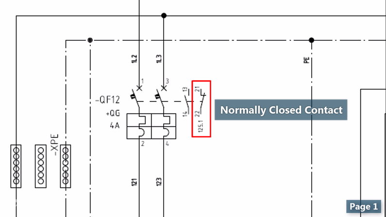
Wiring Diagrams Explained How To Read Wiring Diagrams Upmation

Safety Light Curtain Type 2 Sf2b Ver 2 Discontinued Products I O Circuit And Wiring Diagrams Panasonic

Warehouse Godown Light Wiring Diagram And Connection Procedure In 2023 Electrical Diagram Electrical Circuit Diagram Circuit Diagram
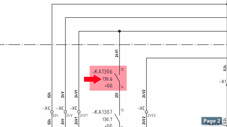
Wiring Diagrams Explained How To Read Wiring Diagrams Upmation
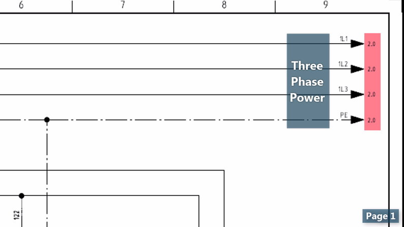
Wiring Diagrams Explained How To Read Wiring Diagrams Upmation
How To Wire 3 Phase

3 Wire 240v Single Phase Power Measurements Eeweb

Ftmmw8vhqrf6bm

Wiring Diagrams For Series And Parallel Circuits Br Carol Fey Plumbing Mechanical
Yamaha R5 R5 Wiring Diagrams
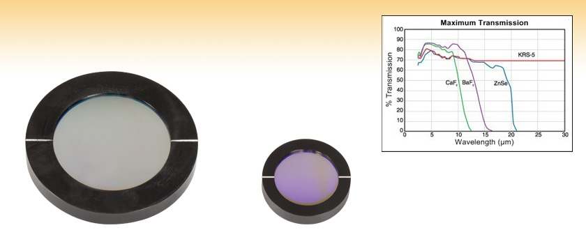
Holographic Wire Grid Polarizers

How To Make Series Parallel Switch Board Wiring Diagram Series Board Youtube